Page 1 Page 2 Page 3 Page 4 Page 5 Page 6
[Page 2]
Harold
Buck and Hewlett worked together at GE on various schemes to put the new
insulator into practical use. Both
men jointly applied for a patent on October 31, 1907, for the construction of a
power line using the new insulator. The
system called for four or five vertical suspension strings and the use of
intervening horizontal dead-ending strings on opposite sides of a crossarm (with
connecting jumper lines). The
periodic use of dead-ending strings would reduce the effects of strains on the
power line due to wind and other factors. The
Buck/Hewlett patent was granted on June 22, 1909.
Mr. Buck also had an article published in the July 20, 1907, issue of Electrical
Review which gave the details of power line construction using the Hewlett
insulator. The first significant
use of the Hewlett insulator was for the new 100,000 volt line of the Grand
Rapids-Muskegon Power Co. strung on 35 miles of steel towers (reported in
November 2, 1907, issue of Electrical World) parallel to the old 60,000
volt line which used pin-type insulators on wooden poles.

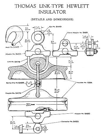
The standard 10-inch
Hewlett shown in the 1920 Thomas
catalog (note
optional hook).
The Hewlett was the first practical suspension insulator and was very much like the modern guy strain insulator in that the two connecting cables or links looped inside the porcelain body in such a way as to make them interlocking. If the insulator broke, the power line would not fall to the ground. The Hewlett patent actually described two different styles of link-type insulators for two different uses -- one for suspension service and the other for strain service. The suspension insulator (for vertical installation) was shown in the patent drawings as Figures 1 and 2 and is identical to the 10-inch disk shown above. The suspension style is what we commonly refer to as the standard Hewlett insulator. The strain insulator (for horizontal installation) was shown in Figures 4 and 5 and is called the “fish-tail” Hewlett because the shape of the outer edge of the disk is V-shaped like a fish tail. Both styles utilized porcelain at its strongest potential -- under compression (from the interlocking link connectors), and, since no cement was used, the Hewlett was free of the problems of cement expansion and insecure metal parts which plagued the cap and pin suspension disks.

Thomas “fish-tail” Hewlett dead-ending string shown in their 1928
catalog.
The
original manufacturer of the Hewlett was General Electric.
The insulators were initially supplied without hardware. The disks were connected into strings by threading cables in
the channels formed in the porcelain and the ends were clamped together with
Crosby clips. Needless to say the
insulator was difficult to manufacture and the interconnecting hardware was
difficult to assemble. The Hewlett
was expensive to make, proved to be fragile mechanically, and was vulnerable to
lightning flashover, which would not only burn the hardware but could seriously
damage the porcelain. Cap and pin
suspension disks were easier to make and assemble and became very popular
between about 1910-1915 until massive failures were encountered due to the caps
and pins pulling out and breakage of the porcelain disk from cement expansion.
The Hewlett quickly regained popularity until the advent of radio
interference caused the design to be abandoned when the problems with cap and
pin insulators were eventually resolved. Usage
of the Hewlett declined throughout the 1930’s becoming obsolete by 1940.
I have observed many Hewletts still in service in the 1980’s and early
1990’s but suspect that many of these installations either have been or will
be replaced soon.
GE
produce the first Hewletts at their Schenectady, NY plant and continued
producing them for a number of years. The
Hewlett became so popular that GE decided to license the patent to the R. Thomas
& Sons Co. in 1917 and to Locke in 1919.
One story relates how Locke gave GE stock in their company in exchange
for license rights to make the Hewlett. GE
gradually withdrew from manufacturing Hewletts and probably stopped making them
by 1925 having transferred all of their interest in Hewletts to Locke’s
Baltimore plant. GE became sole
owner of Locke in 1935.
It wasn’t long until the complicated interconnecting hardware was improved. In 1917, Thomas designed new hardware composed of two copper U-bolts connected with galvanized steel couplers which had a flat spring brass clip inserted in the coupler to make the final secure connection. This unique coupling design became the standard and propelled Thomas’ line of Hewletts into the forefront.

Illustrations of the standard coupler and spring clip shown in 1928
Thomas catalog.


The insulator string at left and the beautiful disk above with unusual tiger stripes are courtesy of Chris Sistrunk. He recovered the insulators from a 115 Kv transmission line owned by the Entergy Co. The line was constructed around 1925. Chris says the crew dismantling the line smash the insulators to get the copper hardware for scrap value.

The
Thomas suspension Hewlett was offered in only the 10-inch diameter size and
advertised as suitable for both suspension and strain service. A typical installation had either 4, 6, or 8 disks connected
into a string but the catalog indicated that up to 15-disk strings were
available. The Thomas
“fish-tail” Hewlett was offered in only two sizes, 6-inch and 7-1/2-inch,
with installations composed of 1, 2, 3, or 4 disks in a string.
The 6-inch “fish-tail” Hewlett was referred to as the “Baby”
Hewlett.

Thomas
Fish-tail Hewletts: 7-1/2-inch (left)
and 6-inch Baby Heweltt (right)

Locke Fish-tail Hewletts: 7-1/2-inch (left) and 6-inch Baby Heweltt (right)
Locke’s suspension Hewlett was 10-1/2 inches in diameter (slightly larger than Thomas’ 10-inch Hewlett). The fish-tail Locke Hewlett came in the standard 6-inch and 7-1/2-inch sizes. Locke used the same interconnecting coupling device and later offered a slightly different version of their own design. Locke Hewletts have been reported with the LOCKE R=¥ insulator logo marking.